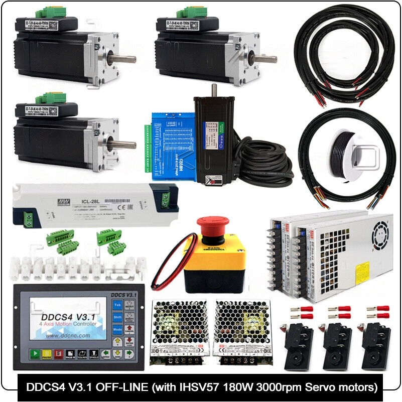
DDCS4V3.1 Controller Bundle with IHSV57 180W Servo Motors HBS57 Motor Drive
$ 98.58
Description of DDCS4 V3.1 Offline CNC Controller DDCS V3.1 is 4 axis motion controller for stepper and servo systems. DDCS V3.1 numerical control system adopts the ARM FPGA design framework. ARM controls the human-computer interface and code analysis and the FPGA provides the underlying algorithms and creates the control pulse. This guarantees reliable control and easy operation. The internal operating system is Linux based. The panel layout structure of the CR8-500 is very rational to save space. All operations are controlled by only 17 keys and a comprehensive G code set is supported. Specifications: 16 opto isolated digital inputs,3 opto isolated digital outputs; Upgrade algorithm,support soft interpolation,fixed arc interpolation bug of the old version; Analog spindle control 0-10V spindle control (can be modified as PWM output); 3-4 axis motor Control.Differential Pulse and direction output signal,Max.500Khz per axis; ARM9 main control chip,FPGA core algorithm chip; 5 inches TFT screen, resolution ratio: 480×272,17 operation keys; 24VDC power input, minimum Current is 0.5A; USB flash disk support for Gcode file input,no size limite of the G-code file; 1GB internal memory; Support standard MPG; Jog function for each axis (continuous, step, defined distance); Support the operation of quickly specify the running position; Support for “Power Cut” recovery. Data is automatically saved; Support the origin and Limit share the same Input ports; The controller only support NPN type limited switch. Appearance and Size: Explanation of Abbreviations When operating the DDCS, the users will come across some English abbreviations.The letters of the abbreviation stand for: FRO: Feed Rate Override SRO: Spindle Rate Override SRJ: Jog Speed Setting F: Feed rate, unit is mm/min S: Spindle Speed, unit rev/min. X: The coordinate code of the X axis. Y: The coordinate code of the Y axis. Z: The coordinate code of the Z axis. A: The coordinate code of the A axis BUSY: The system is busy. You still can adjust FRO and SRO READY: READY mode, any operation can be done RESET: Reset mode, controller is in “OFF” mode, no operation can be performed CONT: Continuous mode, each axis can be manually jogged with the arrow keys Step:Manual Step Mode,each axis can be jogged in defined steps MPG: MPG mode. Operate the machine with the MPG (Manual Pulse Generator) AUTO: Run G code. Auto is showing when file is processing Details of 57HSE3N 3Nm Motor Motor model: 57HSE3N Motor current: 3.5A Output torque: 3N.m Body length: about 132MM Shaft diameter: 8MM, no keyway Outletmode: single output shaft Rated speed: 1000 rpm (no-load speed: 2000 rpm) Outlet mode: two-phase four-wire (must be wired according to motor label) Details of Stepper Drive HBS57 Drive Model: HBS57 (Nema 23, for 57 stepper motor) Pulse Signal: 3.3V/5V/24V compatible. No string resistor required Voltage Range: DC16-70V (New Version: DC24-80, send in random) Subdivision Setting: 800-51200 subdivision The new 32-bit DSP digital 57 closed-loop stepper motor driver, engraving machine, CNC equipment available. PWM current control, low noise, high speed torque is 40% larger than ordinary drives. Mean Well Power Supply Cable Signal Mean Well Power Supply 36V 600W Output Voltage-Channel: 36V Output Power: 597.6W Enclosed Case Input Voltage: 90 VAC ~ 132 VAC/180 VAC ~ 264 VAC selected by switch, 254~ 370 VDC Output Current-Channel: 0~16.6A Input Frequency: 47 Hz to 63 Hz Mounting Style: Chassis Length: 247 mm Width: 127 mm Height: 63.5 mm Mean Well Power Supply – 24V 35W Output Voltage-Channel: 24V Output Power: 36W Enclosed Case Input Voltage: 85VAC to 264VAC, 120VDC to 373VDC Output Current-Channel: 1.5A Mounting Style: Chassis Length: 99mm Width: 82 mm Height: 30mm Input Frequency: 47Hz to 63Hz Unit Weight: 230g Cables 1x 2 core DC cable for motor driver to power supply (Z-Axis) 1x 4 core shielded cable (Z-Axis Driver Signal) 3x 4 core shielded cable (X,Y,A Driver Signal) 3x 2 core DC cable for motor driver to power supply (X,Y,A) 1x 4 Pin EDG through wall connectors 1x 6 Pin EDG through wall connectors 3x 2 core DC cable for E-Stop Switch and controller 3x 2 core shielded cable (X,Y,Z). 1x 12 Row Screw Terminal Block 1x Single Core Hook Up wire. (Black) Limit Switch Kits 3 x Micro Limit Switch 3 x Limit Switch Plate 6 x M3 10mm Cap Head Screw 6 x M5 8mm Cap Head Screw 3 x M5 Drop-in Tee Nut NOTE:The holes in the switch will need to be opened a little (3mm drill bit) to allow for the M3 screw or alternatively you can use a M3 tap to cut a thread into the plastic E-stop Switch Max Current: 10A Max Voltage AC 660V Rated Load: AC: 220VAC/6A, 380VAC/4A, 660VAC/2A DC: 440VDC/0.3A,220VDC/0.5A, 110VDC/1A TYPE: N/C Withstand Voltage: 2500V /60S Temperature: -25°~ 55° Contact resistance:<25mΩ 57 Integrated Servo Motor 180W 3000rpm 57 Integrated Servo Motor Model: IHSV57-30-18-36-01-BY Size: 52 x 76 x 148mm (2 x 3 x 5.8″) Applicable motor: for iHSV57-30-18-36 Input voltage: 20~50V DC (Typical Value 36V) Power: 180W Shaft Diameter: 8mm Torque: 0.6NM Rated Speed: 3000 Impedance: 0.53±10%Ω Continuous output current: 6A Speed response frequency: 50KHz Peak torque: 1.71 Maximum pulse frequency: 250K Default rate: 9.6Kbps (Required external conversion interface) Cooling mode: Natural cooling or forced air cooling Typical applications: CNC, printing, laser, textile machine, etc. Features: ① Full Closed Loop Precise position and speed control to meet the most demanding application requirements. Highly robust servo control can adapt to a wide range of inertial loads and frictional load changes. High-resolution encoder provides accurate position accuracy. ② Low Heating / High Efficiency Adjust the current in real-time according to the actual load conditions to minimize heat generation. The current is almost zero and no heat at rest. Close to 100% torque output capacity, maximizing the energy conversion rate in the most compact space, which is in low power consumption and high efficiency. ③ Smooth and Accurate Based on the encoder space vector current control algorithm, it has excellent performance in the full speed range. Even at low speed applications, it can maintain a smooth and quiet operation. Ensure accurate positioning both during operation and at rest. ④ Exercise Monitoring For some applications where real-time motion has extremely demanding accuracy requirements, JMC servo debugging software provides a simple and practical tool for monitoring the actual trajectory. Can be used to monitor commonly used indicators such as actual speed and position error, as a rating system current actual performance. The interface of interactive monitoring and tuning can get the most optimized performance output as quickly as possible. ALM and PEND Signal Output Ports Control Signal Input Ports Power Interface Port Please Note: For your safety, we recommend to have all high voltage or mains voltage systems be wired in by a licensed electrician. Make sure to have the power turned off when adjusting your wiring. Do not disconnect the stepper motors while power is applied. Package Content 1pcs x 57HSE3N 3Nm Motor with 5-meter Motor Cable and 5-meter Encoder Cable 1pcs x HBS57 Stepper Motor Drive 3pcs x 57 Integrated Servo Motor 180W 3000rpm 2pcs x 2 Core DC Cable for Motor Driver to Power Supply (Z-Axis) 1pcs x 4 Core Shielded Cable (Z-Axis Driver Signal) 3pcs x 4 Core Shielded Cable (X,Y,A Driver Signal) 3pcs x 2 Core DC Cable for Motor Driver to Power Supply (X,Y,A) 1pcs x 4 Pin EDG Through Wall Connector 3pcs x 2 Core Shielded Cable (X,Y,Z). 1pcs x 4 Pin EDG Through Wall Connector 1pcs x 6 Pin EDG Through Wall Connector 3pcs x 2 Core DC Cable for E-Stop Switch and Controller 3pcs x 2 Core Shielded Cable (X,Y,Z). 1pcs x DDCS4 V3.1 Controller 3pcs x Limit Switch Kits 1pcs x E-Stop Switch 2pcs x Mean Well Power Supply 36V 450w 2pcs x Mean Well Power Supply – 24V 35W 1pcs x 12 Row Screw Terminal Block 1pcs x Inrush Current Limiter 1pcs x Single Core Hook Up Wire. (Black)
 GT2 Idler Pulley 20 Tooth Toothless for 10mm Belt
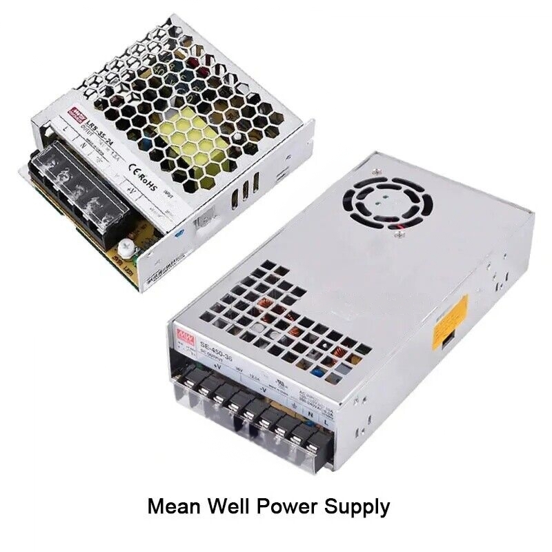 CMT - ER20 PRECISION COLLET D=6,35 (1/4")
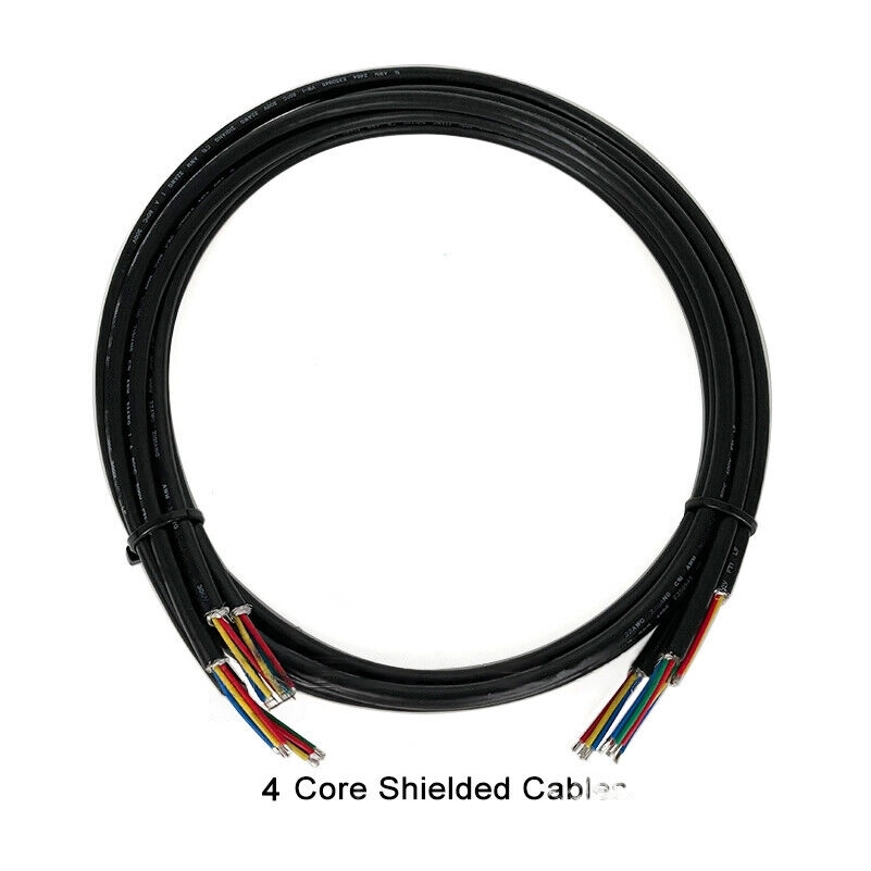 Fineline 3307-BK 7″ Black Plastic Tongs – 3/Pack